
Page 35 - Echotrac E20 SBES
P. 35
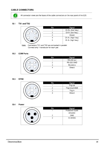
CABLE CONNECTORS


                         All connector views are the faces of the cable connectors on the rear panel of the E20.


                 B.1   TX1 and TX2

                                                            Pin                  Signal
                                                             1               Ch B+ (low freq.)
                                      3                      2               Ch B- (low freq.)
                                  2       4
                                                             3                   Shield
                                  1       5                  4              Ch A+ (high freq.)
                                                             5               Ch A- (high freq.)

                          Note:  Connectors TX1 and TX2 are connected in parallel.
                                 Connect only 1 transducer for each pair.


                 B.2   COM Ports

                                                            Pin                  Signal
                                                             1                 RS-232 out

                                   3      4                  2                RS-232 GND
                                                             3                  RS-232 in
                                   2      1                  4                   Shield


                 B.3   SYNC

                                                            Pin                  Signal
                                                             1                   Trig out
                                   3      4                  2               Trig in/out GND
                                                             3                   Trig in
                                   2      1                  4                   Shield


                 B.4   Power

                                                            Pin                  Signal
                                                             1               Protection Earth
                                                                                (chassis)
                                   3      2
                                                             2                    GND
                                      1                      3                  10-30VDC


                                                                                                                35